Introduction
Railways mobility is a strategic area for business development and growth: all Countries look to infrastructures for moving people and goods in a rapid, safe, and economic way as a key asset, and for this reason are investing many resources.
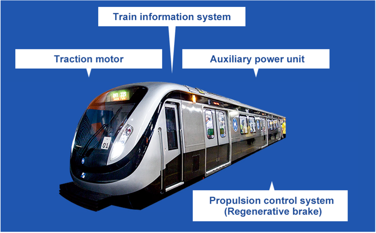
Trains and metros have several electronic components and elements to guarantee their normal functionality.
Therefore, electronic cooling is fundamental and Priatherm, being one of the major heat sink manufacturers, is readily suggesting heatsink design and technology capability to support manufacturers in the traction applications field properly.
Application field
- motors
- batteries
- compressors
- fans
- circuit breakers
Electrical energy, coming from the main overhead line, “enters” the system and needs rectifiers and inverters to be properly managed and transformed to let devices work.
The heatsink is used in cooling electronic devices, to create a mechanical structure for many other smaller elements and to secure the electronic “heart” of the machine to the complete system in movement.
The challenge
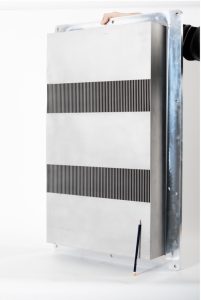
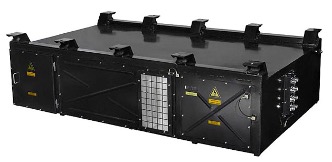
In this specific case, the customer needed a big heatsink to sustain a metal box to be installed on top of the roof of the vehicle: base plate dimensions were approx. 500 x 900 mm. The space available for the cooling fins was max. 120 mm.
Since the requested Rth was lower than 6,5 °C/kW, with forced convection cooling given by axial fans, the fins pack had to be studied, reaching the following optimum: fins thickness 2 mm, height 90 mm, pitch 6 mm, for a total of 74 fins.
Another important input data was that the customer needed a free frame of 50 mm width all around the fins in order to implement a sealing element during the assembly of the heatsink to the main box, able to protect the inside electronics from external agents.
Last point: the surface of the fins had to be resistant to the aggression and corrosion of salty air coming from the external environment.
Solution

- assembly operation step and
- a single cycle in the brazing oven,

Top challenges
- The dimensions of the heatsink: we had to find a solution that would allow us to meet the request, approx. 500x900x120 mm.
- The requested Thermal Resistance, a consequence of high power to be dissipated (6 kW) with a low delta T (40 °C).
- The request to achieve a cost-effective solution to have free space around the fins for applying sealing material and the aggressive environment where the application had to work.
Ask our Experts
Error: Contact form not found.